Rohde & Schwarz PSA5 (Process Controller)
What is it?
A 286 computer plus some unusual interfaces, along with a 9" monochrome (green) monitor inside a 19" case. As the name implies it was supposed to control various equipments.
According to its backplate the following options are installed:
- PSA-B6 · 1006.6659.02 (3.5" FDD)
- PSA-B7 · 1006.7103.02 (40MB MFM HDD)
- PS-B11 · 1006.7332.02 (TTL-I/O-Interface)
- PSA-B3 · 1006.8500.02 (front panel keyboard)
Original configuration:
| CPU | 80286/12MHz |
| RAM | 2MB, separate ICs |
| Video | VGA, ET3000, Green 9" monitor |
| Storage | 40MB MFM HDD (NEC D3142) |
| 3.5" & 5.25" FDDs | |
| I/O | 1 serial (RS-232, 9pin), 2 parallel |
| GPIB Interface | |
| TTL interface + 8 relay outputs | |
| Front panel keyboard with separate card (requires driver in CONFIG.SYS) |
First power-up
After checking that the voltage selector was on 230v I powered it up. I was a little bit surprised to see Award BIOS (I was used to AMI or Phoenix on that vintage). After the usual tests, the expected "CMOS checksum error" message appeard.
Ctrl-Alt-Esc would bring up the typical SETUP menu of the era. Good thing it was included, some older 286s use an external program for seting CMOS values. Of course, there is no provision for HDD auto-detect: parameters have to be chosen from a predefined list of fixed HDD geometries and there is no custom type (47). A look inside revealed that the internal HDD is a 40MB MFM(!) -the model was not visible at the time- so I tried a few typical geometries that would end around 40MB. Type 45 - CHS 642, 8, 17 did work and boot into (German) MS-DOS 5.0.
A quick look around: Norton Commander, Windows 3.0, drivers for the included hardware, some other programs. The front panel keyboard is not working. Also the monitor image has a random flicker: once in a few minutes the picture is compressed vertically for a moment, suggesting a problem with vertical sync or the vertical sweep circuit.
Inside
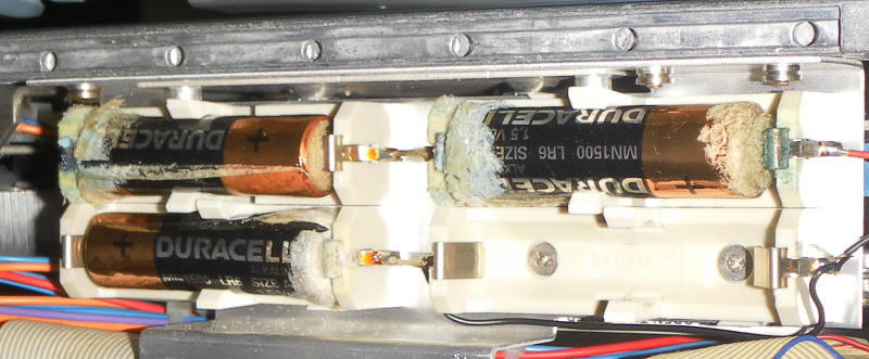
After that short run, it was time for a more careful check of the interior. I was especially worried about the usual problems with old NiCd or NiMH battery on the mainboard, and Traian noticed that the monitor problems were likely related to capacitor troubles.
Rohde&Schwarz proved to have also been cautious about the battery - its position on the MB was not populated, however a small cable went somewhere below. I took off the bottom cover and the full horror was revealed:
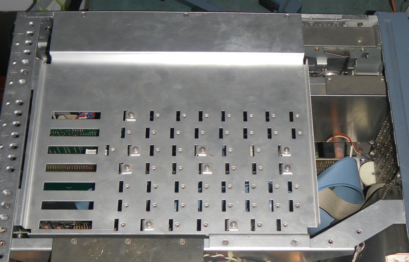
Going back to the "accessing the ISA cards" challenge - I can see no other solution than to remove the rear cover. Some time and 26 screws (2 top, 8 rear, 5 on each side, 6 on the bottom) later, the cover was free. In fact, I took out more, but replaced the ones that were not holding the cover to the case. For those happening to have the same challenge, the following pictures show the screw locations.
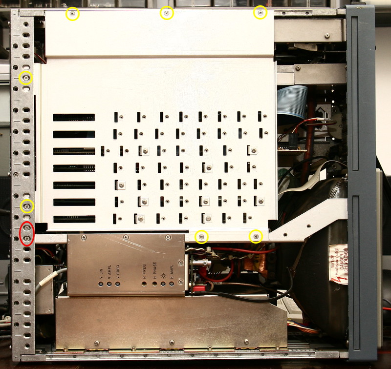
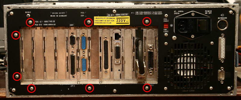
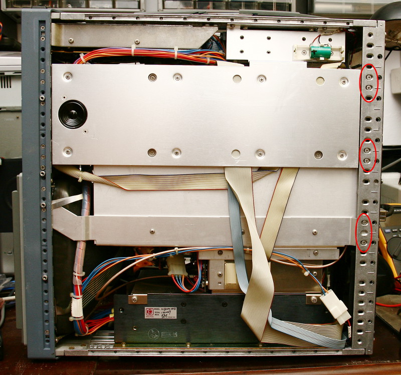
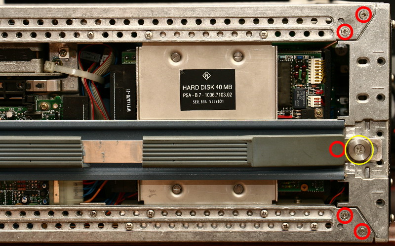
Handle/center screw might be masked by a plastic cover (one was missing on my device)
Why the need to access the ISA cards? Mainly I wanted to install a network card in order to make a full image of the HDD. This being an MFM drive, it's easier than putting the HDD in another computer. The "imaging" of a MFM drive will be the subject of another story.
UPDATE: Reading a MFM HDD, in the context of another story.
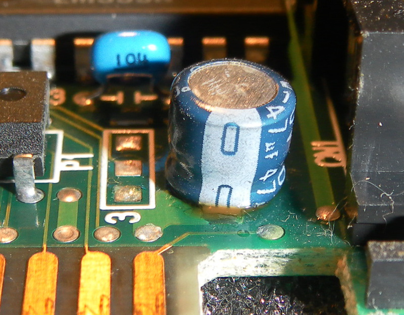
Once I had access, I pulled all the cards out to have a look at them and noticed a serious issue with the VGA card: all the electrolytic capacitors have leaked. I first noticed that the bottom of the card was wet and upon checking it was obvious that all caps have leaked. I know that other equipments from the same era had similar problems, luckily the problem was not very grave. I cleaned the inside of the ISA slot using isopropyl alcohol and a piece of cardboard. I replaced all the capacitors and cleaned the board as well. Besides some small areas where the solder resist was dissolved, the VGA board did not show other damage. I held some hope that the electrolyte could have been the reason for the occasional image flicker but no luck - the flicker seemed to persist. The monitor module is not entirely serviceable, all the HV side is potted and I had another similar equipment with a defect in that part, so that's why I was a little bit anxious about monitor trouble.
Examination of the front keyboard interface led to solving the non-functional front keyboard: the board was configured for IRQ 3, but the CONFIG.SYS driver was configured for IRQ 5. As I planned to use IRQ 5 for the network card and there seemed to be no COM2 port present, I left the (keypad) board on IRQ 3 and modified CONFIG.SYS.
Monitor module
With some reluctance I went for the monitor module. This is quite a tight fit, so I assumed taking it out would not be easy. It wasn't easy, but neither was it very difficult. The only connection I left in place was the HV voltage for the CRT. I'm not sure it was safer this way (in terms of not damaging other components) but I was afraid of damaging either the tube or the connector.
Historical note: Taking out the monitor module I noticed it is made by Knott Elektronik (is it the same as Knott Elektrik?) and the software used for PCB design was tg-CAD (that I did not know about until now), suprprisingly still alive in 2016.
All the electrolytic capacitors measured fine (just a few percent below the nominal value, good ESR). Some air gaps were rather dusty and I cleaned them; however it seems unlikely that that was the cause of the glitches. On the other hand, after taking it apart, cleaning those gaps and assembling it back, the glitches are gone, so who knows?
Another small issue was that the CRT image was slightly rotated; I noticed that the deflection coil was easy to rotate so I was able to adjust it. It is possible that the coil rotated during transport.
Unusual interfaces
It was held not only by the ISA bracket, but also another screw in the top left hole
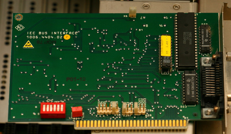
According to the installed software it is supposed to be a National Instruments PC2A interface, however it looks different from what I've seen in the manual. Maybe R&S built their own compatible board?
The software includes a driver, configuration and diagnostic utilities, as well as some libraries and example programs in C, Pascal and BASIC. The configuration utility generates a file called GPIB.COM that has to be loaded as a device driver from CONFIG.SYS (despite its extension it's not a .COM file).
Ports are NEC 71055, it includes a 71054 timer/counter.
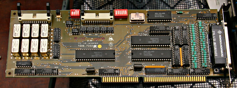
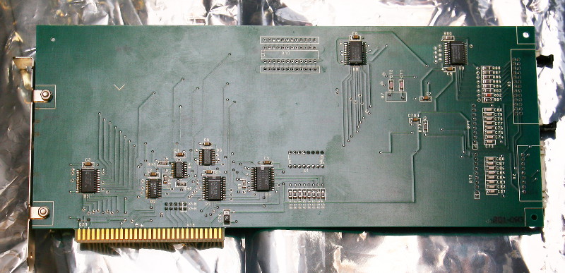
As the name implies this is a multiport (mostly) TTL I/O interface. It does have some opto-isolated ports, as well as 8 relays. The opto-isolated port and the relay outputs go to separate connectors on another braket. I have not checked the pinout and it's unlikely I will ever use it - nowadays it's easier and cheaper to use a microcontroller for any such job. It is however a nice piece of computing history.
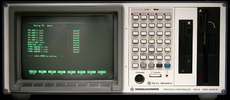
It has its own driver (TTLX.SYS) as well as a RS-BASIC program for internal tests (the BASIC program requires the .SYS driver to be loaded). The result of this BASIC program is shown in the first picture on this page.
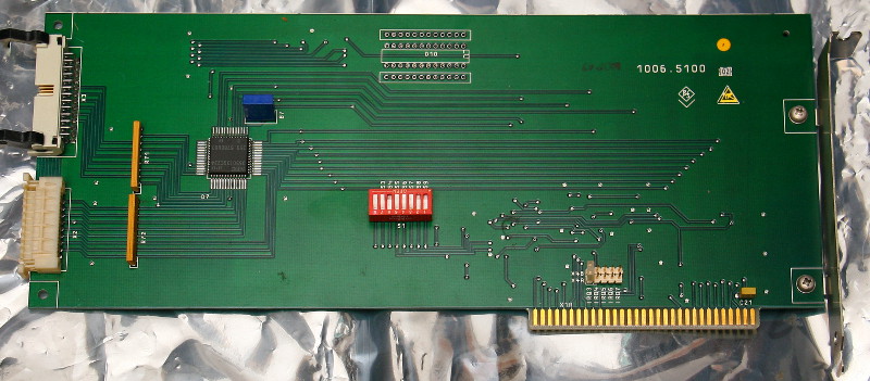
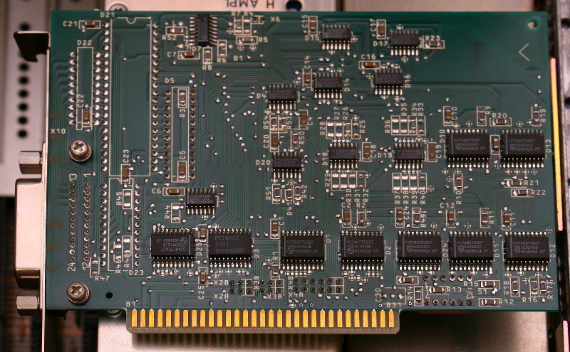
The chip is NEC D65013GC234.
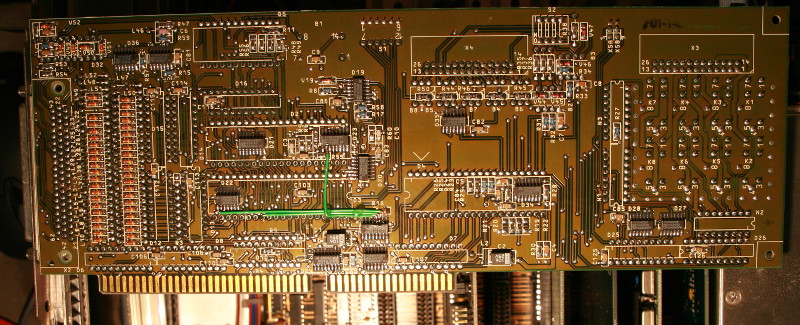
This board interfaces both the front panel keyboard and the 8 keys beneath the monitor screen. It requires its own driver, UDKX.SYS and has its own IRQ. The keyboard is complete (includes keys such as Page-Up/Down, arrows etc), however key combinations such as Alt+Fn do not work. The keys below the screen are just flat, not "touch" as modern capacitive ones and correspond to F1-F8. I'm sure it would have been useful in an equipment rack without a separate keyboard.
I find it interesting that all boards that I found here and are designed by R&S have components on both sides. This is most striking with the keyboard interface, that has lots of PCB area unused, but nevertheless has both sides (sparsely) populated.
Final configuration
I took out the second parallel port (a cheap Taiwan board), and I kept the network card installed. I find it useful to have a working 286 computer with both size FDDs and network connectivity, since I still have lots of diskettes to image/copy and it seems that newer computers (especially with integrated controllers) sometimes have troubles reading old floppies. Having the integrated monitor is a plus (I installed it on a tray in a rack) and the network means it's easy to transfer data from it to the outside world. It works fine with Novell Netware 3.12 as well as NCSA Telnet and FTP.
Published 2016-03-31 by Mihai Gaitos - contacthawk.ro