HC-91, IF-1 and CP/M
First plug in and then see where the smoke appears - adventures with HC-91 and its power supply (included in the external FDD case).
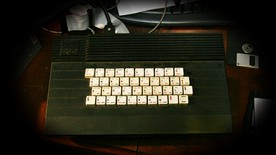
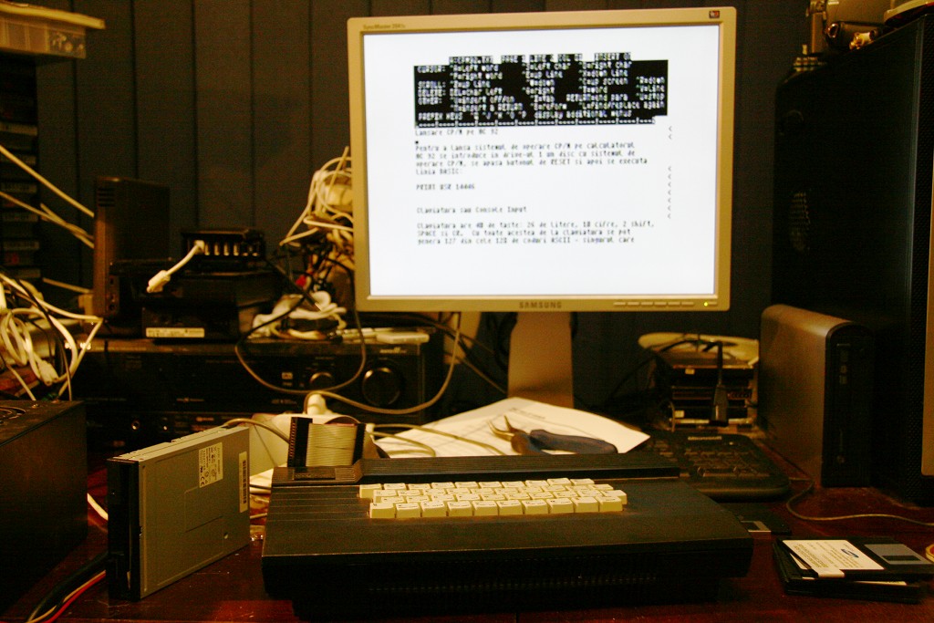
Because of my lazyness and a tendency towards dangerous living, I plugged-in the HC-91 FDD, measured (with DMM only) that it delivers 5 volts for the computer, and connected. After a short search using an oscilloscope I discovered where the composite video out is (DB-9 connector, pin 7), I quickly made a cable that I plugged in my monitor and "Engage". I wrote a small BASIC program to provide the test pattern, just for fun (and test of the PAL encoder).
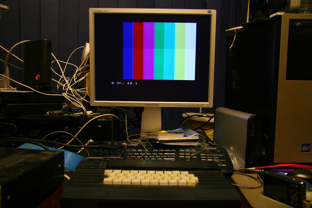
All nice and good, I had a little fun admiring the nice colors (BRIGHT 1 included) and then I wanted to thest the FDD. A short search in the manual provided by Mr. George Chirtoaca (thanks!) showed me how the BASIC commands for formatting a diskette and other operations should look like. OK, let's try. FORMAT and the first surprise: the FDD motor had unstable RPM and the image began to show darker bands as well trouble with horizontal syncronisation (the vertical line between BORDER and PAPER was no longer straight). This led me to think trouble with power supply filtering. Time to get a screwdriver and take a look inside that big black box (FDD+Power Supply).
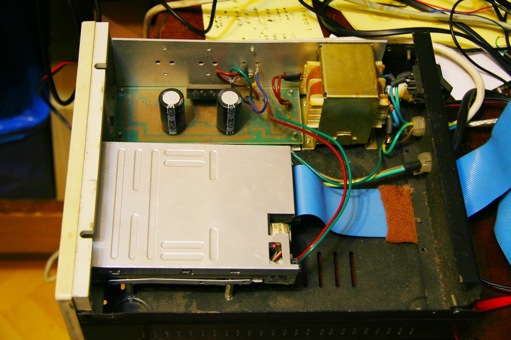
Suprprisingly little! The drive itself only requires 5 volts, so this is the only voltage stabilised by an (assumed) 7805 in TO-3 package (the writing is no longer visible). Well, if I still had the oscilloscope handy, let's see how it looks. I hook a probe (x10) to the output terminal of the 7805 and again I try FORMAT. The result is somewhat unbelievable (at least I have never seen anything likt that so far - it's true that I don't have that much experience either).
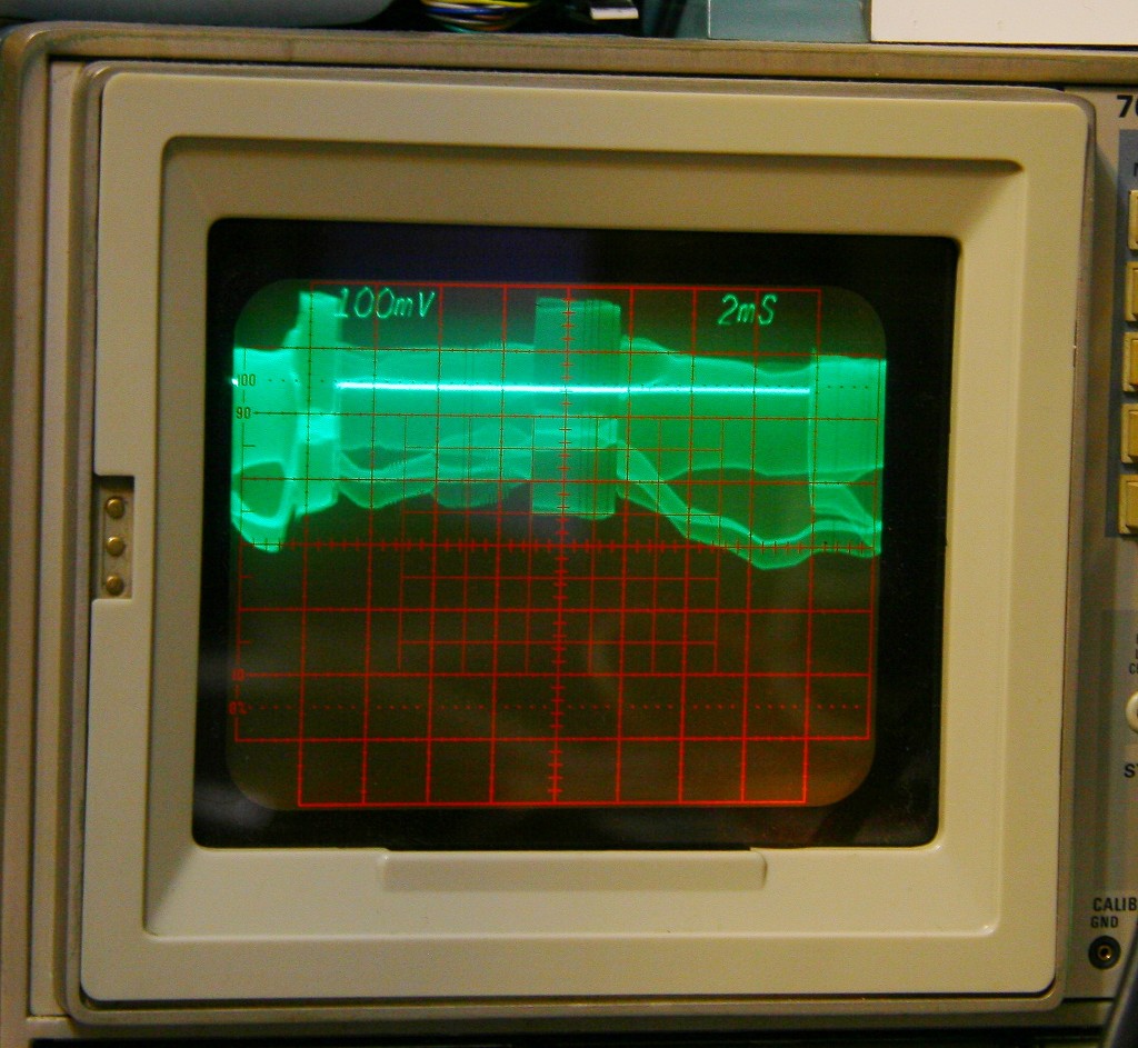
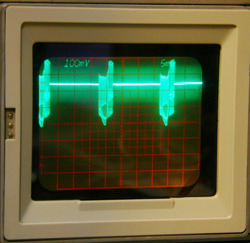
The ripple (can I still name it ripple?) from 3 up to almost 7 volts. (The probe is x10, DC coupled, lowest line on the screen is at -1V). When stable, the voltage is a little above 5 volts, but every rotation of the floppy motor brings this incredible noise. I shut down the supply and took the PCB out to look a little deeper at it. First thing I've noticed is that the bridge was so hot as to be almost untouchable. Secondly (surprise!) I've seen that both electrolytic capacitors were connected in parallel and only filtering voltage after the bridge (on the input side of the stabilizer). The only filtering on the output side of the stabilizer is a small ceramic capacitor soldered to its terminals. I didn't pull it to see the value but I doubt it is relevant.
I *assume* that ths is manufactured in someone's house from "procured" parts. The PCB looks as if it is factory made and destined for a more complex circuit, so I can imagine that someone tried to build a minimal cost version. However the bridge seems too small for this use and the lack of serious filtering on the output side is strange to say the least. I never expected to see something like this.
NB: I tried to use the drive with a well stabilized supply but unfortunately it does not work. RPM is stable when power is good but it seems to have other problems as well. I also tried another (1.44MB - I don't have another 720K one) FDD but to no avail. Meaning that apparently the drive is selected properly - I can hear the seek as it passes from one track to the next while formatting but after FORMAT CAT 1 or SAVE gives an error message along the lines of "disk error".
Update 18-OCT-2012
Using gadjomisu's advice, I covered the DD/HD detection hole of the diskette and this proved to be the sollution for using an 1.44 drive. I mistakenly believed that this is only interpreted by the controller, not by the drive itself. Then a new series of issues appeared with transferring disk images to actual diskettes. Of couse nowadays computers I am using lack even the floppy controller. Besides, at first I thought the transfer would be obvious (dd if=image.dsk of=/dev/fd0 or rawrite) but filesize of the images suggested otherwise. Thanks to George Chirtoaca for software, manuals and informations - the utilities he wrote provided useful and saved a lot of trouble. But even after I found suitable computer (a laptop with Win 98 with DOS mode and a floppy drive) I still had some trouble - it seems that laptop doesn't like 720k diskettes. The FDD has a sensor for DD/HD but something happens since all I get upon verify are read errors.
The next option (desktop, P/75) seems to have its own trouble with the FDD, meaning it doesn't even work with regular (1.44) diskettes.
I kept searching (that's why is good to gather!) and I took out from underneath a stack of boxes a "regular" PC (AT; I had to look for a PS/2-AT adapter for keyboard connection) that had a working FDD. But obviously this was not the end of it. This computer was missing a configured network adapter. Between searching for drivers and a serial connection I opted for what seemed simpler - serial link using Norton Commander. Except when it doesn't work. I don't know why* - a check with term95 proved that the cable and ports were working, so I ended up transfering the files using zmodem protocol at a never before seen rate (~10KBytes/sec). Of course, the only other time I used zmodem was about 15 years ago when connecting to BBSes with a modem. :P
Well, after finally the files were on this computer I was able to create an image of the HC Demo diskette. Demo that didn't work and I don't know why. The error message was NONSENSE IN BASIC after load and something happened which caused the whole program to disappear. I tried loading with MERGE and indeed on line 9100 (the one with the error) was something like:
LOAD *"d";1;"something" CODE LOAD *"d";1;"otherthing"the problem being the lack of ":" between 2 statements. I don't know how/why the problem appeared; apparently at least one other program from that diskette had a similar problem. I forgot to take pictures of this.
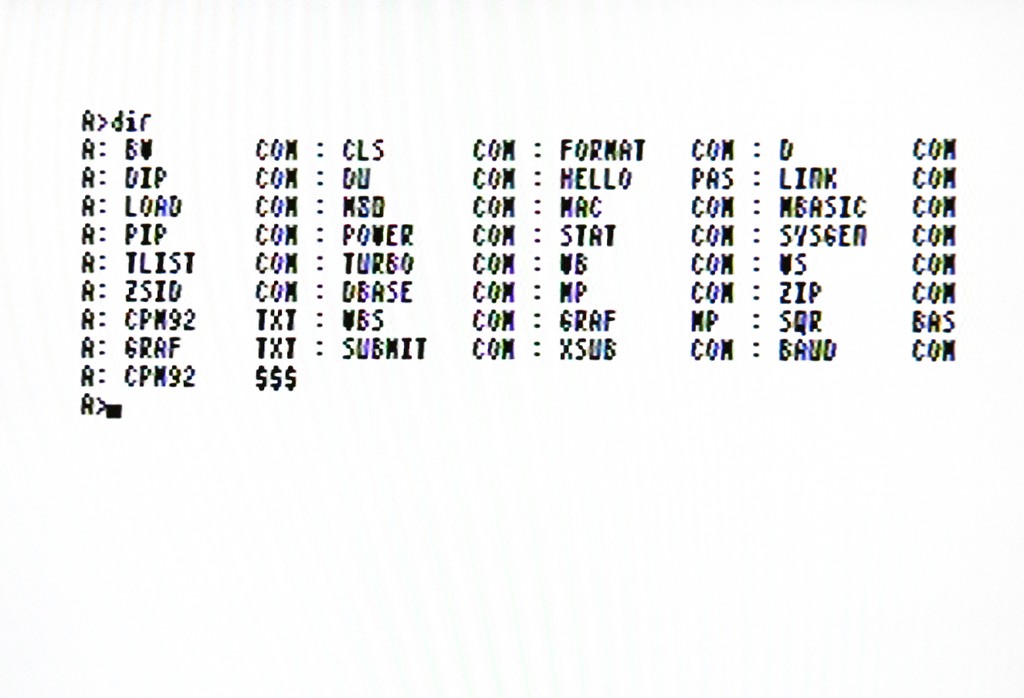
Ok, leave the BASIC alone, let's try CP/M. It seems that the physical format is different between BASIC and CP/M but when trying format+write+verify (using CPMIMG, also by George) it worked.
Victory! We have a working CP/M:
Update 2015
*"What a fool I've been" - the cable didn't work in NC because I forgot to solder together RTS-CTS and DTR-CD-DSR. I realised that in 2015 when I tried using it for something else.
Update 2020
More adventures: Snoopy, HC-91 & Robotron
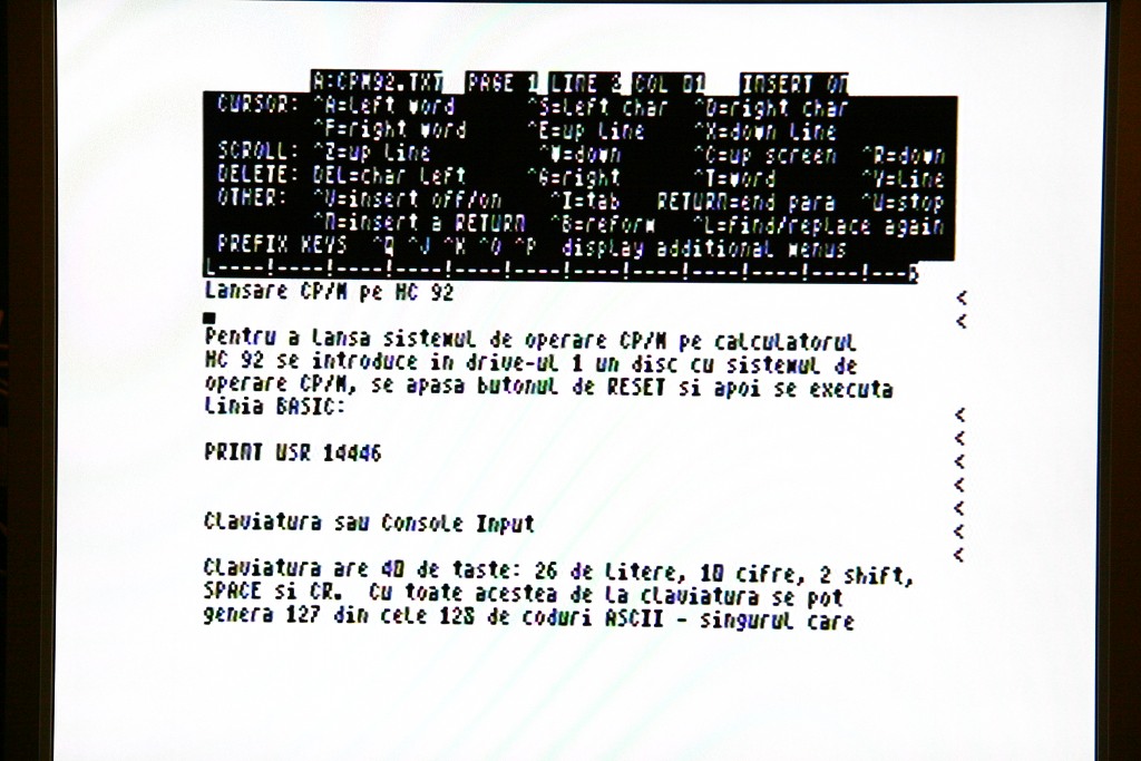
Note, to boot CP/M: PRINT USR 14446
Published in 2013 by Mihai Gaitos - contacthawk.ro