Serial communication for HC-91 with IF-1
When I started my adventure with Snoopy for the HC-91, one of the difficulties I encountered was transferring files between contemporary computers and the HC-91. While this was possible thanks to CPMIMG it was quite laborious. First, I had to build an image file on my regular PC, transfer this to an older computer (running DOS) that has a floppy drive and then write the full floppy image to diskette. Once the files were transferred, it was possible to only use the HC as development machine (and in fact I did that for a while) but the need to transfer yet one more file kept recurring. A simple way to transfer data (even if only text files) between the PC and the HC was clearly needed, not to mention it's a good challenge. The result (sources & disk image) is at the bottom of this story.
Hardware layer
As mentioned in the previous story, the IF-1 does include a serial interface with RS-232 compatible voltage levels but non-standard pinout. The table below shows the pinouts and connections needed to make a cable or adapter:
| HC pin | DB-9 (DCE) | DB-9 (DTE) | Name | Direction (HC) |
| 1 | 8 | 7 | RTS | -> |
| 2 | 7 | 8 | CTS | -< |
| 3 | 2 | 3 | TxD | -> |
| 4 | 3 | 2 | RxD | -< |
| 6 | 5 | 5 | GND | -- |
To make a cable to connect the HC to the PC, use a male DB-9 on HC side and a female DB-9 on PC side (use column "DCE"). If an adapter is needed (say you're like me and keep a NULL-MODEM cable already connected to the PC and plug that to various devices), then use male DB-9 connectors on both ends of the cable and the pinout from the "DTE" column.
First attempt
At first I was under the impression that the huge IF-1 board (it's the same size as the main PCB) would have an UART circuit, seeing as it included a serial port. Sending from the HC to the PC using CP/M function calls was working fine. Receiving, on the other hand, even though it was implemented in the CP/M BIOS, proved problematic. Characters would randomly arrive garbled, suggesting framing errors, even though I went down to slowly typing each character from the sending machine, as well as lowering the baud rate to 2400bps. I asked on RomanianHomeComputer if anybody knew of a transfer program for the HC-91 CP/M (nobody knew) and finally started investigating the IF-1 hardware documentation so I could write my own. At this point I realized that there is no such thing as an UART in the IF-1, merely some level shifters to convert voltages from TTL to RS-232 levels and back. All serial communications are done in software. Bit-banging, so to speak.
Well, that explained the high error rate I was seeing. It seems that the problem is related to interrupts, maybe interrupts are disabled during receiving of a character, but not when waiting for a character. On a software receiver, this might mean loosing the start bit of a character, so everything would be garbled. That meant I had to write my own serial routines.
I started with trying to control the TX line. The main set-back was that the BIOS and maybe some interrupts would reset the serial line. The IF-1 uses the same port (and same bit) for both its "network" interface as well as the serial port. Due to incomplete port decoding, paging the video memory in and out of the address space has the side-effect of switching output to network as well as switching serial to idle. I solved this by disabling interrupts and avoiding BIOS calls in my test routine.
Timing
At the heart of every (asynchronous) serial operation is the baud rate generator. The only available option with this configuration is a software delay loop. The first test (once I got the desired output out of the serial pin) was related to this. I was afraid I might encounter some extra (or worse: random!) wait-states that would disrupt my timings but fortunately this wasn't the case. I tested this simply by toggling the serial port pin through a simple program loop after disabling interrupts and checking the output with an oscilloscope.
Once the predictability of the timings was established, the "quick&dirty" approach was to decide on a baud-rate (19200) and hardcode the baud-rate constant in the program. Not the most elegant way but good enough for now. Knowing the running frequency (3.5MHz1) allowed me to approximate the number clock cycles (T States) needed per bit. T States count can be calculated by dividing CPU frequency in Hertz by the desired baud rate (3500000/19200 =~ 182 T States/bit for 19200bps).
SHLOOP: XOR     A            ; 4  - clear A
        SRL     D            ; 8  - D is shifted right, bit 0 in CARRY
        RLA                  ; 4  - CARRY in bit 0 of A
SBIT:
        OR      E            ; 4  - SET bit 5 (E=00100000b)
        OUT     (0EFH),A     ; 11
        LD      B,CBAUD      ; 7  - BAUD constant
SBITDL:
        DJNZ    SBITDL       ; 13*CBAUD-5 - DELAY LOOP
        NOP                  ; 4  - ALIGN TIMING
        DEC     C            ; 4  - decrement BIT counter
        JR      NZ,SHLOOP    ; 12 - repeat if C!=0
The above loop gives 183 cycles/bit, reasonably close to the calculated value. The serial out port has a bit (network synchronization) that must be set, thus the "OR E" above - E was already set to the needed value before loop start. Along with some code for start/stop bits as well as code for ensuring correct polarity, I had a working TX routine.
Talking is easy. Listening... not so much
Receiving proved slightly more difficult. One problem is the lack of documentation, it's not clear whether it is possible to have an "interrupt on pin change" with regard to serial RX (I assume no), so the receiving code has to keep polling the pin for the START bit and this can lead to slight timing issues. I also wanted to avoid "hanging" forever while waiting for a byte to be received, so I implemented a simple timeout: The RX routine returns after around a second; in fact after it polls the pin 65536 times.
Flow control makes things easier on the HC side: only raise RTS when actively listening to RX and configure the PC to use hardware flow control (RTS/CTS2). However, modern serial ports have some internal buffers and even though they don't start sending while RTS is low, they will keep sending a few more characters after RTS is lowered. What this means is that for "block" receive the total time available between 2 bytes is at most the length of the STOP bit. In my case, for 19200 bps that means at most 182 T States (around 20-30 instructions). Now I understand why some older equipments required the use of 2 STOP bits. Fortunately, my block receive routine seemed quick enough. Once it was done, I decided to test it by receiving an entire "SCREEN" in one block (6912 bytes). Of course, this meant having to discover how to access screen memory from CP/M but that's another story.
Transferring files
My main purpose in this entire adventure was sending files from PC to HC, with some form of error detection. The previous tests proved that even for large blocks transfers were reliable enough so I decided that first version of Xmodem protocol should suffice. The protocol is quite simple and proved reasonably easy to implement; what is more, sx and rx utilities (send/receive Xmodem) are included by default in the Slackware Linux distribution that I'm using, so one side of the problem is already solved. I still ended up writing a simple sx program to verify my CP/M receiving program in face of adversity, such as slow or erroneous transmission.
My RX program (Receive Xmodem) is somewhat rudimentary, it was a good exercise in learning CP/M (e.g. file operations, command line arguments &c). It must be invoked with
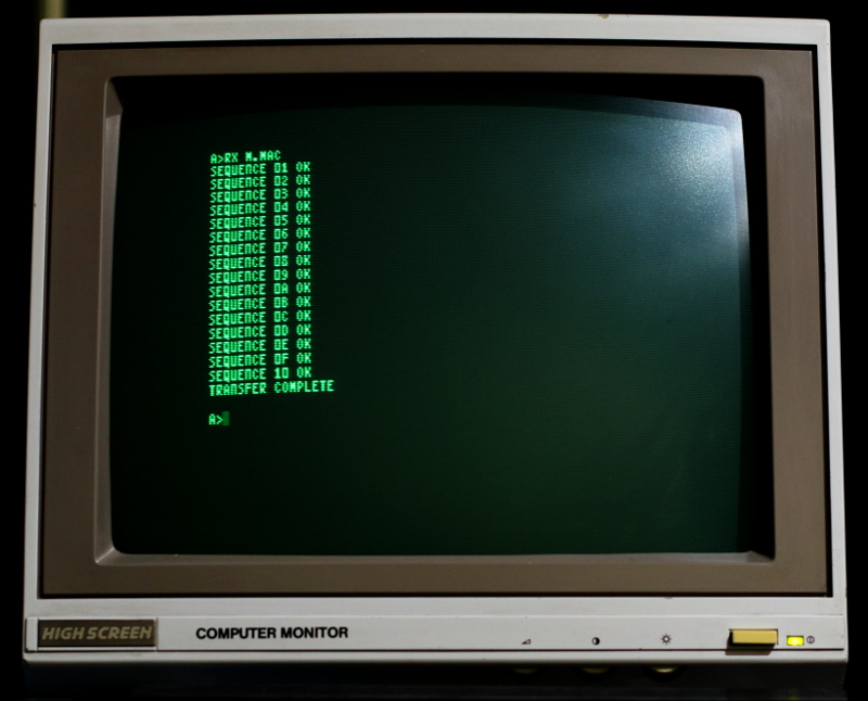
RX <filename.ext>It will start by deleting filename.ext and recreating it, then initiate protocol. Note that Xmodem protocol assumes that sender starts first - when receiver starts it sends a NAK character to sender and waits for a packet. After each packet, it prints the packet number (in hex) and, if the checksum is good, it writes the data to disk and prints OK. (Otherwise, it notifies the user and transmits NAK to sender for a retry).
stty -F /dev/ttyUSB0 19200 crtscts
sx file </dev/ttyUSB0 >/dev/ttyUSB0
rx file </dev/ttyUSB0 >/dev/ttyUSB0
X-modem requires sender to be started before receiver.
stty -F /dev/ttyUSB0 19200 crtscts -icrnl
cat /dev/ttyUSB0 | tee file
tee is used to see the data on screen as well as saving to file. Once the transfer is complete use Ctrl-C to stop.
The end-result
Notes:
- Diskette is bootable and contains sources and binary files. It is included in both raw (.DSK) and IMD formats. It can be written using either CPMIMG by George Chirtoaca (for the raw file) or IMD by Dave Dunfield for the IMD one. To boot the HC using a CP/M diskette, enter the BASIC command PRINT USR 14446 after RESET.
- The programs are meant to be assembled and linked using M80 and L80 (included on the disk image)
The sources archive includes:
- serial.mac - serial routines library, (assemble with M80 to serial.rel and use that to link with other programs)
- m.mac - a collection of simple macros (and a few routines) to make writing CP/M programs easier
- rx.mac - Receive Xmodem
- sx.mac - Send Xmodem
- sd.mac - a simple "send direct" program - it will simply dump file contents to serial (filename required as first argument)
- sa.mac - similar to sd, except will stop transmission at ^Z (DOS / CP/M EOF) - useful for sending a copy of a text file to PC for keeping
- rxscr.mac - receives a block of 6912 bytes in one go and then copies it to video-RAM (used to check that my receive routine would keep pace when continuously receiving large blocks of data)
1 I later realized that for HC the real clock frequency is 3.5468 MHz, meaning that around 184 T States would be required for one bit; however, the difference is small and anyway the delay loop is 183 T States long.
2 I did not bother to check the flow control pin when transmitting; doing this would have required some timeout logic on TX side as well and wasn't really necessary.
Published 2020-12-05 by Mihai Gaitos - contacthawk.ro