Nixie clock
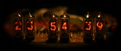
It started with a Nixie display module bought from a hamfest (Friedrichshafen), in 2008, a module that included the Nixie tubes and 74141 drivers. No HV supply, no documentation of any kind. The module included 10 tubes, 2 of which were letters and simbols (M,m,G,u;Hz,V,A,Ohms), 8 with numerals.
At that time it just seemed an unusual type of display and I thought it would be an interresting challenge to try and use it for some purpose. A clock was the obvious choice, since it seemed quite simple to implement. At the time I had almost nonexistent electronics knowledge (besides the basics; e.g. I did know what a transistor did but did not know how to connect it, drive it, etc). Since I write software for a living I thought the simplest way would be to use a microcontroller, but it wasn't something I was familiar with. However, one of the books I found at the ARRL booth (still in Friedrichshafen) was "PIC Basics" (by Cliff Powlesland, G8CQZ) and I bought it thinking it would provide some useful pointers to microcontroller programming. It was a good choice, as it had some electronics instructions along the way.
I believe that trying to create something from scratch is a better learning experience then simply copying something that already exists so I decided to create my own design.
My "adventure" was made easier by the fact that the display module already had the drivers connected to the nixies; after some searches on the internet I have found the datasheet for the 74141 drivers (thanks Dieter - I think your site was one of the first to provide such information back in 2008), so by following traces I could figure out the module pinout. I also found the datasheet to the tubes and figured out the needed voltage. I used a 220-110v transformer (I live in a 230v country - close enough) and found the resulting 160v dc to be enough to light up the tubes.
The first test (I did not know if the module would work or not) was to simply power it up with HV and see what happens - all digits litup. I figured that I should pull the inputs to ground so I did that, connected all but one input to ground and indeed one digit was lit. This test was done with the inputs for all drivers in parallel, so in fact it was one digit for each tube. I then started experimenting with the uC. I have bought the kit recomended in the book (Velleman K8048) and the 2nd example provided with the kit was enough for what I wanted to do next.
Since there were 8 tubes, I connected them in 2 groups of four, to drive them from the 8 bit port of the PIC uC. This seemed to work, as well.
Along with the kit, I bought a few TTLs, including some 74LS373 registers, to experiment with. Well not much in the way of experiment - their use seemed pretty straightforward.
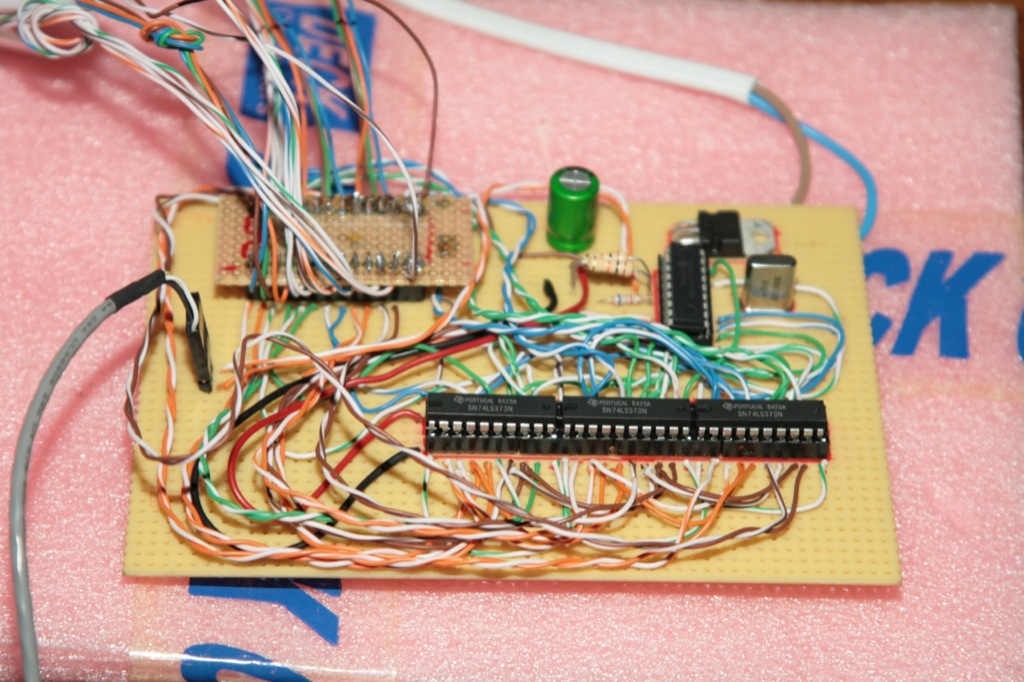
The approach was as follows - I used 3pcs 74LS373 registers to maintain the outputs. All PORTB pins from the PIC were used to connected to the input of the registers (8 bits) while 3 PORTA pins were used to SELECT each register. The datasheets (along with some ideas picked up from the book) were enough for me to manage to get a different digit lit up on each tube. After that it was just a matter of programming to get a clock running. I added two buttons for setting hour and minute and everything was pretty much working. By the way - I used the 4MHz crystal as timebase as well, setting up a timer in the PIC that would "tick" every 100ms and this proved surprisingly precise. I suspect this has to do with minimising the crystal error - with the counter running at 1MHz (F/4 for PIC) I had good resolution in compensating for the (very small) crystall error. One other thing to note here - I used one of the PIC timers, not a delay loop. However, I did not want to bother with interrupts at that time, so I simply checked the timer overflow in a loop.
Relevant code:
MAIN
; just pass the time for about 10 miliseconds (on timer1)
		BTFSS	PIR1,0  ; overflow is on bit 0 of PIR1
		GOTO	MAIN    ; if not set wait some more
; if set, then reset timer
		MOVLW	VALTH	; constants preloaded with counter value for 4MHz xtal
		MOVWF	TMR1H
		MOVLW	VALTL
		MOVWF	TMR1L
; clear overflow
		BCF	PIR1,0
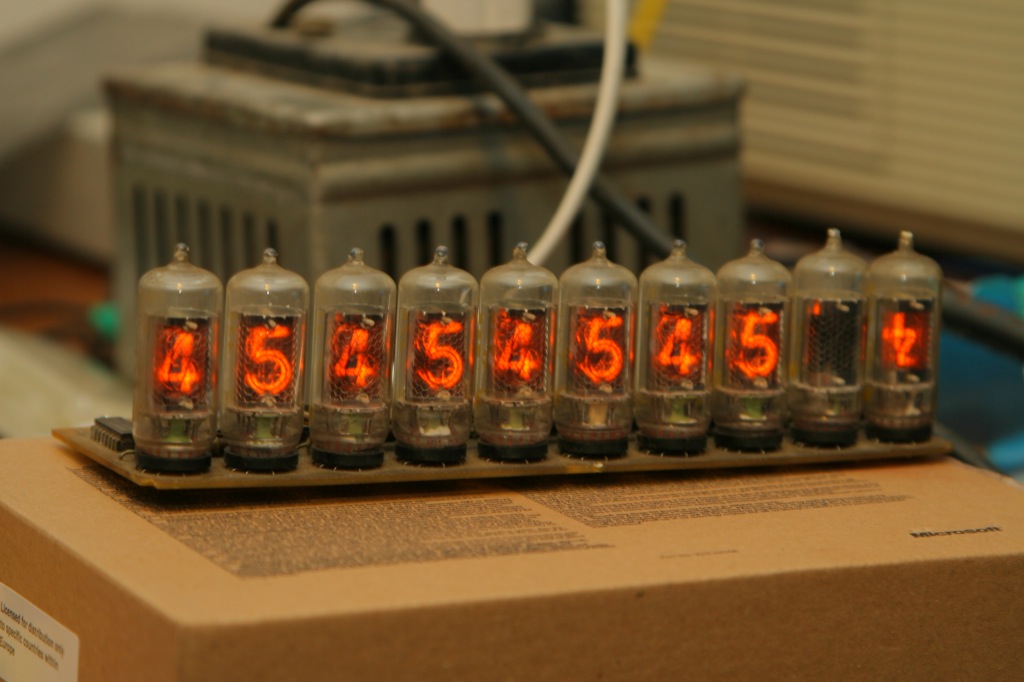
 First prototype, that in fact ended up in daily use with only slight modifications.
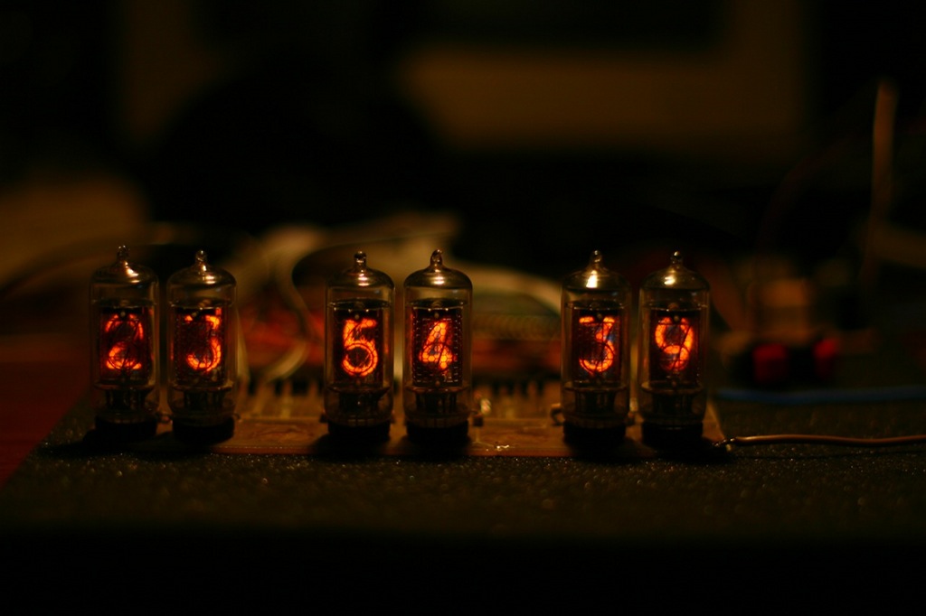
Eventually I had a nice nixie clock but with a big bulky transformer from 220v to supply the tubes and a separate supply for logic side. This part took a little over a week of vacation (but it was more than full time work - from wake-up until going to sleep I was working on this - learning electronics in the process). However this also sparked an interest in electronics that has not subsided yet.
In the end. the design is obviously primitive and lacking all of the features of other clocks have (most annoying being lack of battery backup, since we tend to get power failures around here). I have planned for the past 3 years to design and build another, more advanced one, but there are always some other things that get in front. By the way, besides the power supply (which by itself took some months in all) the case proved a difficult challenge. In the end it's only two black pieces of plywood with holes for the tubes - just as primitive as the rest. The 2 rectangular buttons for Hours and Minutes (what was in my mind to pick rectangular ones? I think it was the only thing I found at the time) are dangling from a small wire. But it's the first physical thing that I created (software seems so ephemeral). And for almost 5 years (until I published this) it has worked flawlessly in our bedroom. It stays on at all times (except when we are on vacation) and still works, although the tubes (which were rather degrader to start with) are showing signs of old age (digits are no longer complete, but still readable).
Power supply
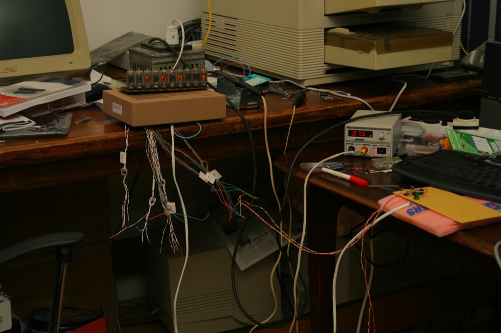
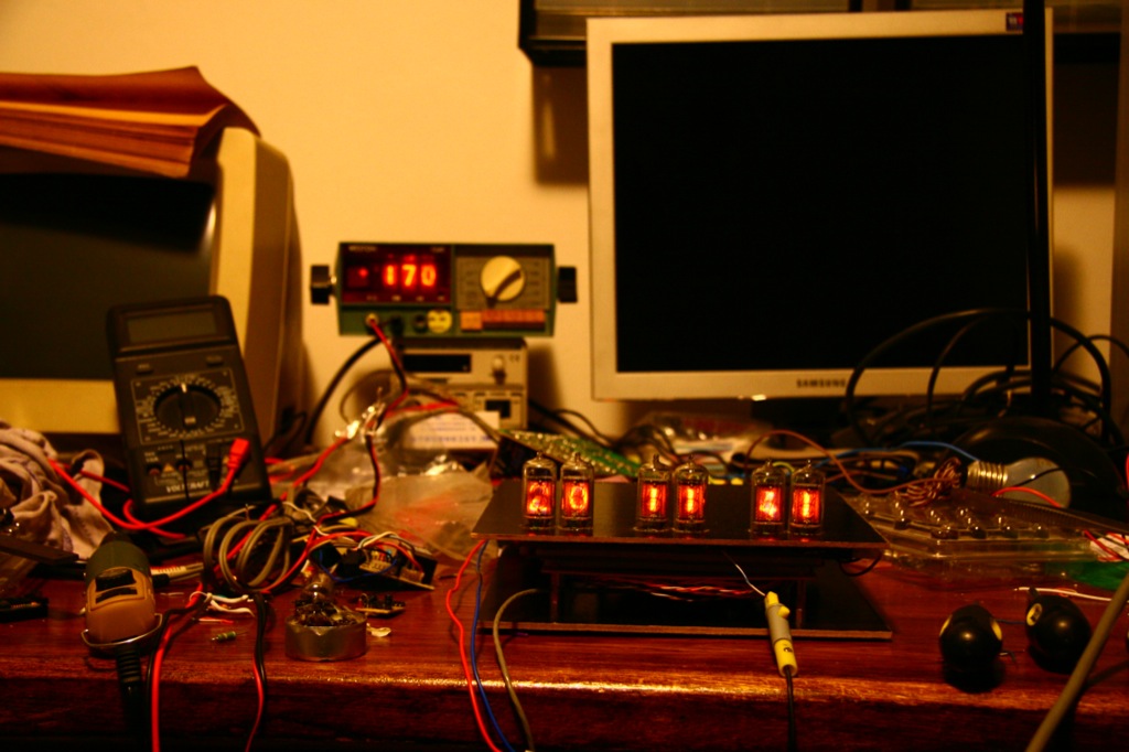
I wanted to have the whole assembly powered from a "wall-wart". Of course, one option would have been to use unregulated AC output adapter and put another transformer inside. However this did not appeal to me, I wanted to build a "proper" SMPS. Well.. proper is quite an exageration - typical SMPS IC have rather strict requirements and need various other components around. In keeping with the primitive (in this case naive) but functional principle which seems to define this project, the supply is a simple oscillator that is only running when HV is below a certain reference (set using multi turn variable resistor in series with another fixed one). The naive side is that the oscillator is yet another PIC (the cheapest and simplest one I found then - 10F200, IIRC). No 555 timers or multi-vibrators, and, of course, no PWM. My reason for this approach was the low price of the PIC (similar to a 555, in fact) and the comfort of not needing to search for appropriate values of other passive components to get the desired frequency and duty cycle. The first idea was to use the "main" PIC to provide switching pulses but it seemed that some mistakes in the "clock" code could cause destruction of MOSFET or - worse - unchecked raise of the HV voltage with all the unpleasant consequences that would have. Whilst using a separate PIC (that lives in fact on a separate PS board) helps keeping things nicely separated and seemingly secure. The rest of the power supply is rather simple: a MOSFET from an old (and defective) ATX power supply, along with the stand-by transformer from the same ATX PS. I didn't have a suitable inductor, and the transformer small enough to fit in my "case" even though it is somewhat "overkill".(The multimeter behind - used here to check the anode voltage for the Nixies - is using Nixie tubes itself. It was a gift - thank you Peter - either to use the tubes or itself. When I checked and saw that it was still working, I chose to keep it intact and use it for its original purpose)
 Old gallery with some additional images
Published in 2013 by Mihai Gaitos - contacthawk.ro